What are PCB assembly drawings?
What are PCB assembly drawings?
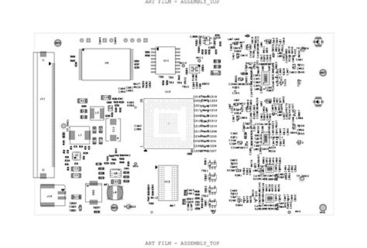
The fabrication drawing will include information on how the raw printed circuit board is to be built, while the assembly drawing will include details on how the components will be attached to that raw PCB. In either case however, you will start from the same place with these drawings; in your PCB design tools.
What are fab notes?
Suggested Fabrication Notes Fabrication notes allow PCB Designers to take control of not only design but also to determine the fabrication process regarding the end product.
What is PCB drill drawing?
A Draftsman Board Drill Drawing View is an automated graphic composite of the active PCB project’s board outline and drill holes. The view is rendered with definable symbols that correspond to hole types and also includes any specified drill layer pairs.
What is Fab assembly?
The fabrication drawing contains information on how to build the printed circuit board (PCB). While your assembly drawing depicts details on how several components are going to fit on the raw PCB.
What is Fab layer in PCB?
The fabrication layers are used to display the simplified mechanical outline of components on the PCB. KiCad refers to the fabrication layers as: F. Fab – Front fabrication layer.
What is Gerber file and what is the use of that?
The Gerber format is an open ASCII vector format for printed circuit board (PCB) designs. It is the de facto standard used by PCB industry software to describe the printed circuit board images: copper layers, solder mask, legend, drill data, etc.
How do you make Gerber in Altium?
Generating Gerber file
- Open your .PCB design files on Altium designer software. Select File -> Fabrication Outputs -> Gerber Files.
- General Setting. In the General Setting set the precision to 2:5 (0.01 mill resolution)
- Layers Setting.
- Aperture Setting.
- Advanced Setting.
How do you make a drill file in Altium?
How to Generate NC Drill File by Altium Designer? In the main interface of Altium Designer, click File>>Fabrication Outputs>>NC Drill Files sequently and come to NC Drill Setup dialogue in which options need to be specified including NC Drill Format, Leading/Trailing Zeroes, Coordinate Positions etc.
How do you make a hole in Altium?
We can create mounting holes in Altium Designer in two ways. Create a mounting hole as a common object using Place > Pad from the main menus. After creating a pad, we need to configure its type (through), the exact size of the hole, the metallization area, and manually assign a net to it.
What are the 5 Classification of assembly drawing?
General assembly drawings, showing an overall assembly. Outline assembly drawings, showing the exterior shape. Diagrammatic assembly drawings, representing the assembly with the use of symbols. Unit assembly or sub-assembly drawings, showing in more detail a part of the overall assembly.